|
Experiment 3 : Voltage Standing Wave Ratio and Standing Wave
Components
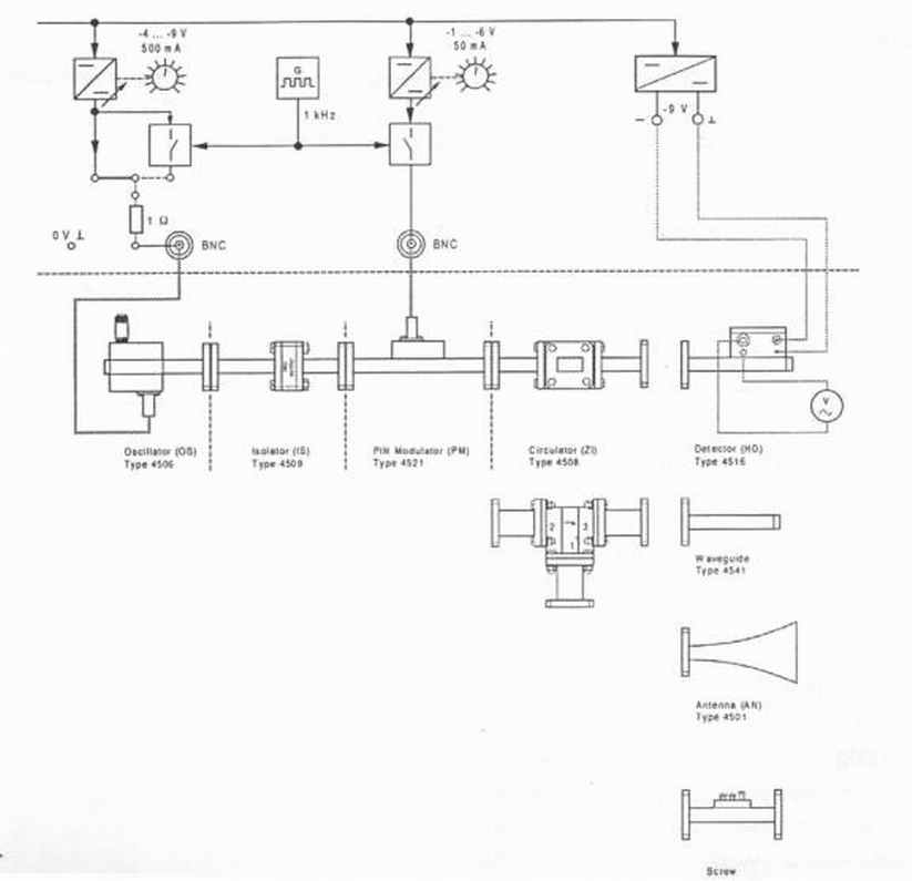
and measuring equipment 1 Microwave Trainer Type 4510 1 Oscillator (OS) Type 4506 1 Circulator (ZI) Type 4508 1 Isolator (IS) Type 4509 1 Detector (HD) Type 4516 1 Pin Modulator (PM) Type 4521 1 Waveguide Termination (HR) Type 4541 1 Antenna (AN) Type 4501 1 Sliding Short-Circuit (KV) Type 4546 1 Screw Transformer (TG) Type 4551 1 Connecting plugs and leads Series 9100 1 Multimeter
Experiment Setup
Figure 1.7: Circuit set up for VSWR measurement.
Experiment procedure Set up the circuit according to Figure 1.7 Set the potentiometer for the voltage supply of the Gunn oscillator to centre position V= (-8V) Plug the 4mm connecting plug, so that the supply voltage of the Gunn oscillator is not modulated. By turning the micrometer screw, set the Gunn oscillator to a value of 14.5 GHz. Connect the PIN modulator to the voltage source modulator and set the potentiometer of the modulator to the left stop (-1 V). Apply a bias voltage of –9V to the detector. 1.
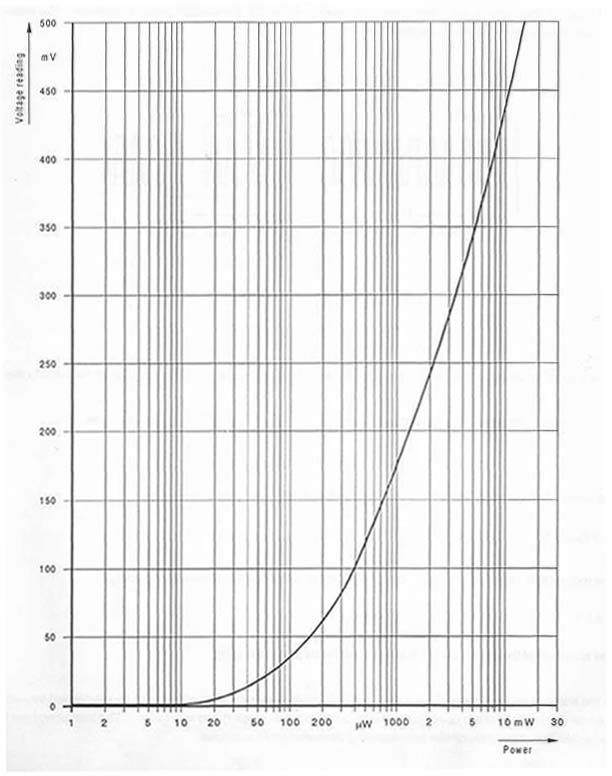
Measurement of outgoing power, Pva. To measure the outgoing power, Pva, connect to detector to gate 3 of the circulator and terminate gate 1 with the terminating impedance. Turn the potentiometer for the modulator voltage to the right hand stop (full power) and read the voltage on the detector. With the use of Figure 1.10, find the related power value. Vva = mV, Pva = mW 2.
Measurement of the reflected power, Pa with terminating
impedance connected. Connect the terminating impedance to gate 3 and the detector to gate 1 and read the voltage Va proportional to reflected power, Pa (Use Figure 1.10) Va = mV, Pa = mW 3.
Measurement of reflected power Pvo with open line Remove the terminating impedance from gate 3. Vvo = mV, Pvo = mW 4.
Measurement of reflected power Pf with a strongly
mismatched line connected Connect the sliding transformer at gate 3 (screws unscrewed so that they do not protrude into the waveguide) and then the detector to it. The mismatching is altered by the additional line. Now read the voltage indicated by the detector as a reference value: Vvf = mV, Pvf = mW Turn one (or more) screw(s) in so that the voltage indicated on the detector decreases by about one third. Switch over the waveguide termination and the detector so that the detector is connected to gate 1. Read the reflected voltage Vf at the detector: Vf = mV, Pf = mW 5.
Measurement of the reflected power Pan with a horn antenna
connected. Mount a horn antenna at the output of the circulator. Remove all objects out of the antenna’s beam angle of departure to avoid any reflections from the environment: Van = mV, Pan = mW Calculate the power ratios of every component of the reflected to outgoing power as a numeric value, Pa / Pva i.e. the power reflection coefficient, ρ2 and the voltage reflection coefficient, ρ : ρ
a2 = ,
ρ a =
. ρ o2 = , ρ o = . ρ f2 = , ρ f = . ρ an2 = , ρ an = . Calculate the VSWR, s and the inverse standing wave ratio, m: s
a =
, m a =
. s o = , m o = . s f = , m f = . s
an =
, m an =
. Questions and discussions 1. Describe the following terms: a. Matching/mismatching b. Inverse standing wave ratio, m c. Reflection coefficient d. Standing wave e. Voltage standing wave ratio (VSWR) 2. In power measurement, attention was draw to the fact that considerable measuring errors may occur due to different inverse standing wave ratios of load (mv) and power head (detector), mm. Assume mm is equal to 1, then use the following formula to calculate the measuring error F for all the cases.
F = [ mm (1 – mv)2 ] [ mv (1 + mm)2 ] 3. Discuss the whole experiment.
|