|
Experiment 4 : Matching Impedance
Components
and measuring equipment 1 Microwave Trainer Type 4510 1 Oscillator (OS) Type 4506 1 Circulator (ZI) Type 4508 1 Isolator (IS) Type 4509 1 Detector (HD) Type 4516 1 Pin Modulator (PM) Type 4521 1 Waveguide Termination (HR) Type 4541 1 Sliding Short-Circuit (KV) Type 4546 1 Screw Transformer (TG) Type 4551 1 Connecting plugs and leads Series 9100 1 Multimeter
Experiment Setup
Figure 1.8: Circuit arrangement for the impedance measurement Experiment procedure Setup the circuit as shown in figure 1.8. Set the potentiometer for the voltage supply of the Gunn oscillator to centre position (V= -8V). Plug the 4 mm connecting plug so that the supply voltage of the Gunn oscillator is modulated. Turn the micrometer screw at the value of 1.25 mm. The frequency value can be obtained from the first part of the experiment (Frequency measurement using frequency meter). Connect the PIN modulator to the voltage source modulator and set the potentiometer of the modulator to right stop (-6 V). Apply a bias voltage of –9 V to the detector.
The impedance of the non-matched experiment setup can be established by calculating the VSWR from the ratio of Pmax / Pmin and subsequently the m circle. Turn out the screws of the screw transformer, so that they no longer protrude into the waveguide. Search for the place of maximum mismatching (highest indication Pmax) between two minimums by shifting the sliding short circuit. Also search for minimum mismatching. Read off the values respectively for Vmax and Vmin. Vmax = mV , Pmax = mW Vmin = mV , Pmin = mW Calculated the m, s, ρ2 and ρ with the measured values (with the aid of experiment 3). Second
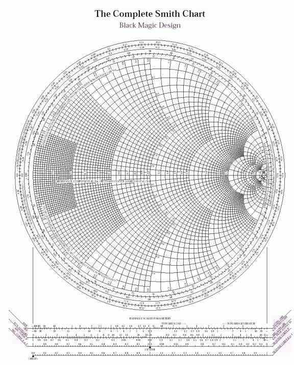
part You need a guide wavelength of λH for the second experiment. As you are using the frequency for the micrometer screw setting at 1.25 mm, the λH can be taken from experiment 2. Draw the m circle as in Figure 1.9, which you have established in the first part of the experiment. Point A, for example, which results from point of intersection of the measured, m circle with the value l/ λ = 0.11 may serve as stating point for further calculations. Calculated the value of the line length, lAB to reach a point B on the m-circle from which transformation can take place to point 1 (ideal matching) with a series C. lAB = cm A point C could be reached with longer line section from which a direct matching could be achieved with a series L. Calculated the length of this line to get from A to C. lAC = cm Calculated the line sections with the aid of the guide wavelength, λH and the ratio l/ λ from figure 11. l/ λAB = cm, l/ λAC = cm Questions
and discussion 1. Simply describe the usage of Smith diagram. 2. Why is it in the experiment, oscillator is supplied with DC voltage and what are the purposes of using PIN modulator and circulator in this experiment. 3. Briefly describe the interferences from the experiment. |