|
Experiment 1 : Frequency Measuring with Resonance Frequency Meter Components and measuring equipment 1 Microwave Trainer Type 4510 1 Oscillator (OS) Type 4506 1 Isolator (IS) Type 4509 1 Frequency Meter (FM) Type 4531 1 Detector (HD) Type 4516 1 Connecting plugs and leads Series 9100 1 Multimeter
Experiment setup
Figure 3: Measurement set up for frequency measuring.
Experiment procedure First, set the micrometer screw of the Gunn oscillator to the value indicated on the label to obtain a frequency of 14.5 GHz (1.5mm). Set the potentiometer for the voltage supply of the Gunn oscillator to centre position (V≈ -8 V) and plug the 4 mm connecting plug, so that the supply of the Gunn oscillator is modulated. Tune the resonance space to resonance by turning the micrometer screw of the frequency meter until the measured voltage is clearly minimised.
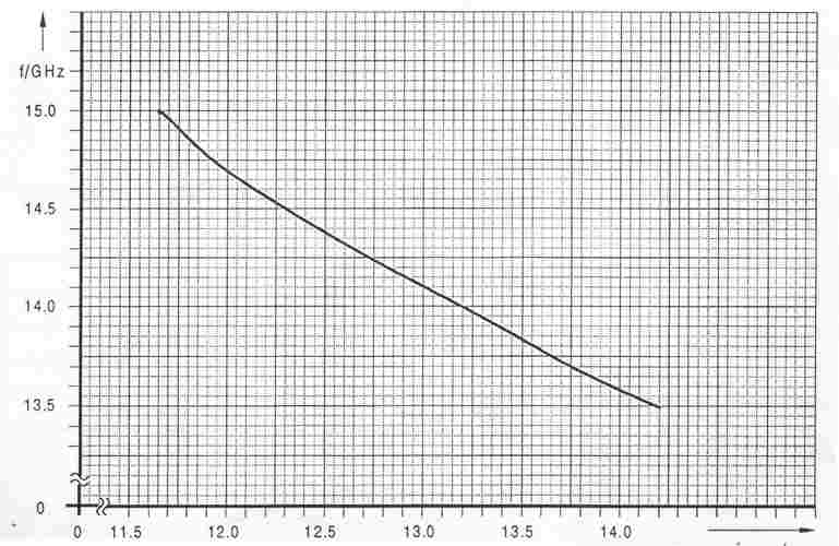
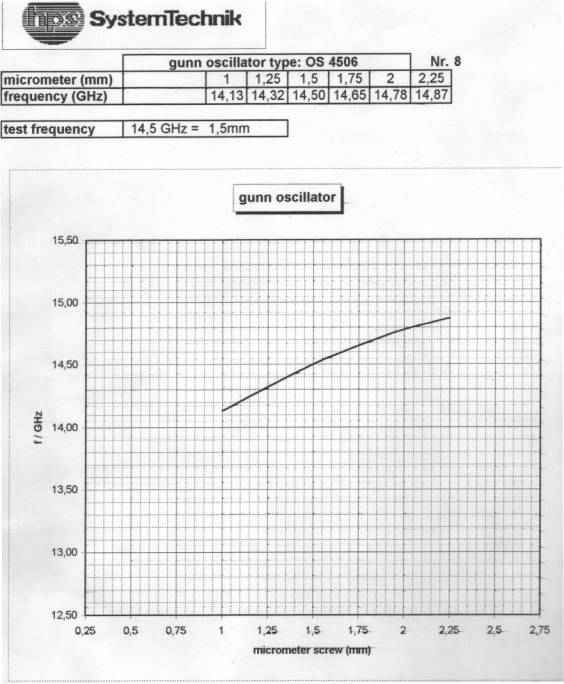
In principle, the display in scale subdivisions can be converted to operating frequency with the aid of figure 1.3. To minimise measuring errors, every frequency meter is supplied with its specific scaling characteristic. Change the frequency of the Gunn oscillator by turning the micrometer screw of the oscillator by 0.25mm to the right and the left. Compare the results with the Gunn oscillator data sheet as shown in the figure 1.4. Results
Questions 1. Give a simple discussion regarding the operation of resonant frequency meter in this experiment. 2. Calculated the error (deviation) between the frequencies obtained using the resonance frequency meter and the frequencies from the oscillator data sheets.
Figure 1.3 : Scaling of frequency meter
Figure 1.4 : Oscillator data sheet |