|
Equipments
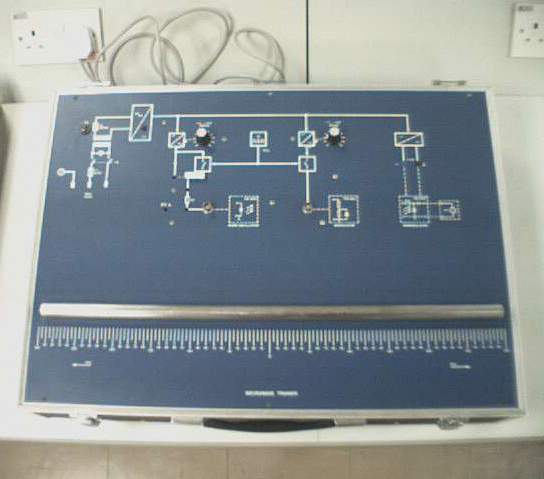
Microwave Trainer (Type 4510)
Front View
Figure 4 : Front view of Microwave Trainer (Type 4510)
Mains Connection Mains voltage: 230 VAC/115 V AC, 50 … 60 Hz, 20 VA Mains switch: ON/OFF with pilot lamp Mains fuse: F1 = 0.1 A slow (at 230 V), primary side F1 = 0.2 A slow (at 115V), secondary side Power is supplied through a 3-pin appliance connector on the rear side of the unit. Change-over from 230 V to 115 V (110 V) mains voltage is done by resoldering jumpers (0 W resistors) inside the unit (see fig.1). Warning: Before dismantling the unit pull the mains plug! Oscillator Current Supply The oscillator current supply alternatively supplies a continuous signal or meander-from signal clocked with 1 kHz, the voltage of which is continuously adjustable by means of a potentiometer. Selection is done by plugging in a 4 mm connecting plug. The current consumption can be measured as a voltage value via a 1 W resistor and afterwards be calculated. Voltage range: -4 V … -9 V Max. Current: 500 mA Fastening Screws The unit can be screwed out of the case by loosening the six fastening screws. Warning: Before dismantling the unit pull the main plug! Modulator Signal Amplitude of the modulator signal continuously adjustable by means of potentiometer. The signal is a meander-form voltage clocked with 1 kHz and used for the PIN Modulator (Type 4521). Voltage range: -1 … -6 V Max. current: 50 mA Constant Voltage Source High-ohmic voltage source. It supplies a constant bias voltage for the Schottky diode of the VSWR Detector (Type 4556). Voltage: -9 V Mounting Rail Mounting rail for setting up experiments with the components Length: 60 cm Scale Millimetre scale for accurate positioning of the components on the mounting rail.
|