|
|
|
|
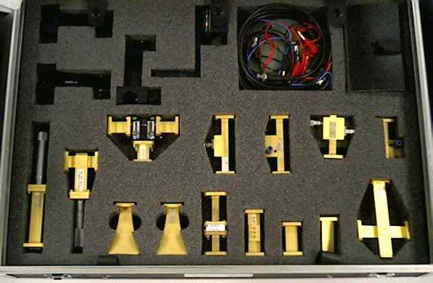
Waveguide
Holder (Type 4501.2)
Connecting elements (3 pieces) between Waveguide (Type 4514) and mounting rail, with snap-in device and setscrew.
|
|
|
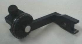
Rotary connecting element between Antenna (Type 4501) and mounting rail, with snap-in device, set-screw and graduation.
|
|
|
PIN
modulator for modulating the continuous wave signal in the signal branch. Modulation factor: approx, 90 %.
|
|
|
Leads: - 1 mains lead, 2.5 m - 2 connecting leads, F = 2 mm, length; 0.5 m - 1 HF connecting cable with BNC connector, 1 m Material Samples (Type 4519): The material samples are used for attenuation measurements and for proving the polarisation of a wave. - 4 EPOXY plates (dimensions: 130 x 130 x 2mm). Three plates are copper-plated (different patterns). - 1 holder for plugging in the Material Samples
|
||
|
The output power of the Oscillator can be mechanically adjusted in the range of 14.25 … 14.75 GHz. Its signal is available at a waveguide output via a WR 62 flange (R 140). Output power: 20mW at 14.5 GHz
|
|
Storage of the Connecting Elements Storage box for storing the following connecting elements supplied with: - 30 fitted screws - 30 knurled nuts
|
||
|
Detector (Type 4516) The detector is designed as a sensor for incoming signal. It operates as an absorption power meter. A bias voltage can be applied via external connections. This considerably increases the sensitivity.
|
|
|
The VSWR Detector, designed as a continuous waveguide piece and equipped with a Schottky diode, enables measuring of the ripple in the signal branch. Matching, however, is altered noticeably by current consumption of the diode. This detector is therefore more used for monitoring. For accurate measuring, use of the Circulator (Type 4508) is intended.
|
|
|
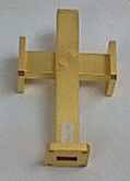
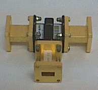
The Cross Coupler can be used for checking the forward of reflected wave. It is designed as a multi-slot coupler, which enables compact construction because of its good directivity. Coupling attenuation: approx. 20 dB
|
|
|
|
Waveguide
Termination (Type 4541) The Waveguide Termination is designed as a waveguide and piece with pyramid shaped absorber and therefore achieves very good matching.
|
|
|
With the Waveguide the length of the electrical line can be changed. Length: 50 mm
|
|
|
Sliding
Transformer (Type 4551) The Sliding Transformer enables both improvements in the matching and almost unlimited mismatching. It is equipped with three screws about 7 mm apart. The screw-in depth is more than 70% of height of the waveguide.
|
|
|
The Isolator is use for protecting the oscillator in the experiments setup. In addition, largely independent of the matching of the series-connected components, is achieved. - Insertion loss: ca. 0.5 dB - Blocking attenuation: > 20 dB
|
|
|
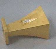
The two Antennas are used in practical experiments for determining the antenna diagram when one of the two antennas is mounted on the Antenna Holder (Type 4501.1)
|
|
|
Sliding
Short-Circuit (Type 4546) With the Sliding Short-Circuit the electrical line can be changed in length by about 50 mm. The movable part is terminated additionally with a l/4 trap.
|
|
|
The Frequency Meter operates in the range of about 12.5 GHz … 15.5 GHz as a resonant frequency meter.
|
|
|
The Circulator enables measuring of the reflected signal independently of the measuring setup and without inserting additional probes in the signal path. This means that measurements of reflections of radiated power are possible using only one Antenna (Type 4501).
|
|
|
|
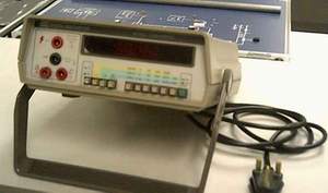
Multimeter is used for displaying the value of Voltage, Resistor and Current.
|
|